This document explains how to do animations in OpenGL based on skeletal animation. The basic idea is to define the skin mesh once, and then only update the bones position. I will not show how to create the buffers (VBO) and uniforms, which is readily available elsewhere. Instead, I concentrate on how to interpret and prepare the animation data. In principle, animation is implemented in four steps:
1. Use a tool, e.g. Blender, to create an animation.
2. Load the data in the initialization phase of the application, transform and pre compute as much as possible.
3. For every frame to be drawn, use interpolation to compute a transformation matrix for each joint.
4. Let the shader do the final transformation of each vertex (skin section), as depending on the joint matrices.
Step one is only needed once, of course. Step two can conveniently be done by a custom conversion tool, and saved in a special file. Blender was used for creating the models. There are lots of tutorials about this, so I am not going to go into many details. For some background to animation and skinning, see Animation in video games by Jason Gregory.
Any comments are welcome, I will try to correct or improve.
Model file format
I use Assimp to load the model files. There are many possible formats that can be used, and it is not obvious which one is best. In a commercial project, consider using a custom format. This has the advantage that loading will be quick, and the files will be harder to copy. Also, the main application doesn't need to know about file formats of 3D modeling applications.
The easiest format is probably the .obj format, but it does not support animations and bones. I use the Collada (.dae) file format. Make sure not to use the pre transformation flag for vertices (aiProcess_PreTransformVertices), as this will remove the bones data.
Definitions
This is a list of definitions used below:
bone matrix: The resulting skinning transformation matrix you'd upload to the vertex shader.
offset matrix: The matrix transforming from mesh space to bone space, also called the inverse bind pose transform in Assimp.
node matrix: a node's transformation matrix in relation to its parent node.
bind pose and rest position: The original position of a model.
frame: One complete picture rendering.
The words "bone" and "joint" are used now and then, but really mean the same in this text.
Bind pose and current pose
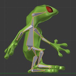
The bind pose is the rest position; the position where no animation has been applied. This is the position the meshes get when the influence of the bones are ignored. The current pose is one frame in an animation. The bones information in the node tree (pointed at from the aiNode) defines the bind pose of the skeleton.
Assimp data structure
Arrows represents pointers, and the blue dashed arrows represent references by name or index.
Mesh dependency of bones
In rest position, each mesh has a transformation matrix that is relative to its parent (as defined by the node tree aiNode). However, when doing animations, there is instead a list of bones that the mesh depends on. The offset matrix (in aiBone) defines how to get the mesh position in relation to these bones. When the animation bones are in rest position, the resulting transformation matrix will be the same as the mesh transformation matrix (in aiNode). If there is more than one mesh, a bone may be used more than once, with different offset matrices and weight tables for each mesh.
Every vertex in a mesh can depend on several joints. This is defined by the aiBone list in aiMesh. This list is a sub set of all bones, restricted to those that have an effect on the mesh. To make the shader program efficient, it has to have a reasonable limit on the number of joints. In my case, I want to limit this to at most three joints. Assimp has support for this, using the flag aiProcess_LimitBoneWeights with
importer.SetPropertyInteger(AI_CONFIG_PP_LBW_MAX_WEIGHTS, 3);
Key frames and interpolation
An animation is like a movie; there are a number of frames every second. Using 24 frames every second would require a lot of data. Instead, only key frames are used, and interpolation in between. The key frames can be defined at irregular time intervals. A movement of a bone consists of three parts: scaling, rotation, and translation. The scaling is usually not needed, but rotation and translation are. Interpolating translation movement is trivial, as the translation is linear. To convert from a key frame data to a transformation matrix, I use the code as follows. Scaling, rotation and translation, are values copied from the scaling key, quaternion key, and position key, respectively, and coded as the corresponding glm type.
aiVector3D ScalingKey;
aiQuaternion RotationKey;
aiVector3D PositionKey;
glm::vec3 s(ScalingKey.x, ScalingKey.y, ScalingKey.z);
glm::quat q(RotationKey.w, RotationKey.x, RotationKey.y, RotationKey.z);
glm::vec3 t(PositionKey.x, PositionKey.y, PositionKey.z);
glm::mat4 S = glm::scale(glm::mat4(1), s);
glm::mat4 R = glm::mat4_cast(q);
glm::mat4 T = glm::translate(glm::mat4(1), t);
glm::mat4 M = T * R * S;
Rotation is coded as quaternions. That means that interpolation is efficient and of high precision. However, OpenGL uses 4x4 matrices for transformations. Interpolation with matrices (also called linear blend skinning) work well with scaling and translation, but not for rotation. For example, interpolating a rotation that is only given with two points 180 degrees from each other will cut a straight line through the origo instead of following the arc. The interpolation of rotation need to be done before the quaternion is converted to a matrix to avoid this problem.
There is a performance problem with using interpolation on quaternions between key frames. The interpolation itself is very quick, but the problem is the bone parent/child dependency. The interpolation has to be done for every bone. When combined with the scaling and translation, it will generate a new transformation matrix that is relative to the parent node. To get the final transformation matrix (the bone matrix), the result has to be multiplied with the parent node, etc., all the way up to the top node. Finally, the offset matrix has to be applied to each of them. This is a lot of work to do on the CPU for every frame that is going to be drawn. If interpolation is done only on transformation matrices, it is possible to pre calculate each matrix (from aiNodeAnim), including the offset matrix. It is a simplification I am using, which adds the requirement on the models to have a sufficient number of key frames when describing rotations.
Animation preparation
For a frame in an animation sequence, the bone (and mesh) positions defined in the node tree (aiNode) are not used. However, the information about parent/child relations is still needed. Instead, new positions are defined by aiNodeAnim. For every bone (called channel in aiAnimation), there are a couple of key frames. Problem is, this bone depends on the parent bone. That is, a bone defined in aiNodeAnim has a position defined relative to the parent node. As every bone can have different number of key frames, at independent times, a bone position may depend on a parent bone that does not have a defined position for the same key frame. To simplify, it was decided that all bones shall use the same number of key frames, at the same times.
When exporting animation from Blender, set the model is in rest position. Otherwise, the mesh offset matrices in the node tree (aiNode) will be set to the current bone position, instead for the rest position of the bone. You will want to toggle this mode back when working with the animations. It doesn't change the result of the animation, but it helps to debug if you want to compare to the rest position.
 |
| Dopesheet |
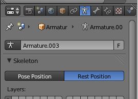 |
| Rest position |
Blender and bones
Blender has the 'z' axis pointing upward. Bones in Blender have they have their own coordinate system, with 'y' is pointing in the direction of the bone. That means, when an upright bone is added as seen from the ‘z’ axis of Blender, that the bone will have the local coordinate system where 'y' is up. This corresponds to a rotation of -pi/2 on the 'x' axis to get to the Blender space. That means that a rotation transformation is needed when using bones for animations. This is done automatically, and created in the export file from Blender. A typical result is a transformation matrix:
1 0 0 0
0 0 1 0
0 -1 0 0
0 0 0 1
This matrix will set the y value to the z value, and the z value to -y. It is possible to enable the display of the bone's local coordinate system in Blender in the Armature tab, "Axis" checkbox. These rotations, and counter rotations, unfortunately make it a little harder to debug and understand the matrix transformations.
Notice that OpenGL doesn't have the same coordinate system ('z' is by default pointing out of the screen) as Blender, which means that you eventually will have to make a model rotation of your own. If you don't, your models will lay down on the side.
Matrix multiplication
Exporting to Collada format from Blender usually gives a node tree (aiNode) as follows:
Scene
..Armature
....Bone1
......Bone2
..Mesh
Mesh matrices are relative to the Scene, and has to be computed just like the bones. If that isn't done, all meshes will be drawn over each other, at the same position.
Each node inaiNodeAnim has a matrix that transforms to the parent node. To get the final transformation matrix of Bone2, a matrix multiplication is needed: Scene*Armature*Bone1*Bone2. This is true for the bind pose, as well as for the animations of bones. But when computing animation matrices, data from aiNodeAnim is used and replace the data from aiNode. When testing that animation works, start with defining an animation at the same rotation, location and scaling as the bind pose. That would give bone replacement matrices that are the same as the originally defined in aiNode.
The above matrix multiplication gives the final matrices for each bone. But that can't be used to transform the mesh vertices yet, as it will give the animated locations of the bones. The mesh absolute rest position is Scene*Mesh. Instead of using the mesh transformation matrix from the node tree, a new mesh matrix is computed based on the bones and an offset. There is a matrix that is meant for exactly that, and it is the offset matrix in aiBone. The new mesh matrix is Scene*Armature*Bone1*Bone2*Offs. This is the bone matrix that shall be sent to the shader.
Animation shader
This is the animation vertex shader, with functions irrelevant to animation removed.
uniform mat4 projectionMatrix;
uniform mat4 modelMatrix;
uniform mat4 viewMatrix;
uniform mat4 bonesMatrix[64];
in vec4 vertex;
in vec3 weights;
in vec3 joints;
void main(void){
mat4 animationMatrix =
weights[0] * bonesMatrix[int(joints[0])] +
weights[1] * bonesMatrix[int(joints[1])] +
weights[2] * bonesMatrix[int(joints[2])];
gl_Position = projectionMatrix*viewMatrix*modelMatrix*animationMatrix*vertex;
}
bonesMatrix: Up to 64 joints can be used in a model. It is a uniform, as the same list of bones is used for all vertices.
vertex: This is a vertex from the mesh that is going to be animated by 0 to 3 bones.
joints: The index of three joints for the current vertex.
weights: The weights to be used for the three joints. There is one set of weights for each vertex.
Debugging
To debug the application, you can do as follows
- Change the shader so as to use the identity matrix instead of bones matrix. That should draw the mesh in bind pose.
- Do the same thing, but use bone indices to make a color in the fragment shader. That way, you can verify that the right bones are selected by the indices.
- Instead, use weight information to make a color, that way you can test that the weights are correctly transferred.
To help debug an animation application, there are tools where matrix multiplication can easily be tested. I use Octave for this.
Column major and row major
The expressions column major and row major denotes how a matrix is stored in memory. OpenGL and glm use column major, DirectX and Assimp use row major. glm is the math library used in the Ephenation project. This isn't much of a problem, except when a conversion from one to another is needed. The most effective conversion would have been to simply copy 16 consecutive floats for a 4x4 matrix when converting from Assimp aiMatrix4x4 to glm::mat4, but it won't work because of different layouts in memory. I used the following:
void CopyaiMat(const aiMatrix4x4 *from, glm::mat4 &to) {
to[0][0] = from->a1; to[1][0] = from->a2;
to[2][0] = from->a3; to[3][0] = from->a4;
to[0][1] = from->b1; to[1][1] = from->b2;
to[2][1] = from->b3; to[3][1] = from->b4;
to[0][2] = from->c1; to[1][2] = from->c2;
to[2][2] = from->c3; to[3][2] = from->c4;
to[0][3] = from->d1; to[1][3] = from->d2;
to[2][3] = from->d3; to[3][3] = from->d4;
}
Edit history
2012-06-21: Added suggestions on how to debug.
2012-06-29: Added information about creating transformation matrix from assimp key frame.
2012-07-25: Correction of "offset matrix" definition. Correction of matrix order in key frames interpolation, improved example and improved explanation of the LBS problem. Clarification of Blender bone orientations and matrix multiplications. Thanks to Dark Helmet for pointing these out!